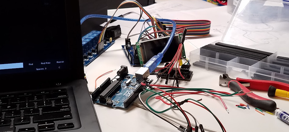
Daisy Chaining SPI on the Arduino Mega 2560
While working on a new revision of a project, I moved from an Arduino Uno to an Arduino Mega. In theory these devices should handle SPI in the same manner, just with different pins. While MOSI, MISO, and SCK are on pins 11, 12, and 13 respectively on the Uno, those change to 51, 50, and 52 on the Mega. I initially daisy chained two LTC2400 analog-to-digital modules onto the SPI bus, just like I had them on the Uno, but immediately ran into issues.
Using SPI on the Arduino Mega
Interestingly, SPI does seem to work fine on the Mega in test cases. If you attach the bus to pins 51, 50, and 52, then run a chip select (also called slave select, CS, or SS) line to the provided pin 53, this seems to function with no issues. Pull the CS low, then read from MISO, no problems at all. It turns out that CS on 53 is actually more important than you might think when doing daisy chaining, but more on that in a moment.
PORTB and Chip Selects
Many SPI devices will use cbi() and sbi() functions to clear and set bits directly on port registers of the Arduino, which has a number of advantages like resulting in smaller code, much faster switching, and the ability to switch multiple pins at the same time. The pins on the Arduino are divided into ports logically, such as PORTA, PORTB, etc., which can be seen nicely in this diagram. If you were to want to rapidly switch pin 0 on PORTB on, you would initially set its direction bit high to make it an output, then set its port bit high to bring its voltage high.
// Set bit 0 on register DDRB (direction, port B)
sbi(DDRB, 0);

// Set bit 0 on register PORTB (port pins, port B)
sbi(PORTB, 0);
It follows then that I/O standards on the Arduino are usually grouped into a single port, which is the case on both the Uno and the Mega. On the Mega, MOSI (pin 51) is PORTB 2, MISO (pin 50) is PORTB 3, SCK (pin 52) is PORTB 1, and SS (pin 53) is PORTB 0. This keeps everything cleanly on the same register, but with SPI it may not always work out that way. If you’re daisy chaining SPI devices, there’s only one pin 53. You’ll need to use an additional pin as an extra SS line, and that pin may not be on the same port.
Where is PORTL?
As Hao Jiang found in this post about Arduino Mega port mapping, not all ports on the Mega even seem to respond to changes in their respective registers, so unless you’re okay with using pinMode() and digitalWrite() in your SPI code, the SS options are preemptively limited. Just get ready for this to begin with–where you want that SS line may not be where you get that SS line. But that’s not the most vexing issue you’d have to debug.
The Tyranny of Pin 53
Put simply, you can’t use it if you ever want more than one SPI device. I don’t recall ever having this issue on the Uno, but on the Mega, MISO only seems to become available if pin 53 (the SS it knows) transitions to low. This leads to a few problems:
- If one device is on 53 and another is on 49 (or any other number), you can contact the one on 53, but will receive nothing on MISO when transitioning 49 to low.
- If you transition 53 to low at the same time, you’ll get traffic, but it will just be a collision.
- If neither device is on 53, then neither of their SS lines when transitioned will initiate anything over MISO.
The Solution to Daisy Chaining
My theory is that in the Mega, MISO (and maybe MOSI–I wasn’t using a device that needed that line) is inextricably linked somehow with SS on pin 53, and traffic can only be received on MISO if SS also transitions to low. The solution, then, is to use different pins as SS lines (on a port register that actually works) for each daisy-chained device and when flipping their SS low, also flip 53 low even though nothing is connected to it. When flipping any SS to high, also flip 53 to high. This seemed to be a foolproof way to get data from each device.